Meeting Point in Wire Drawing Dies
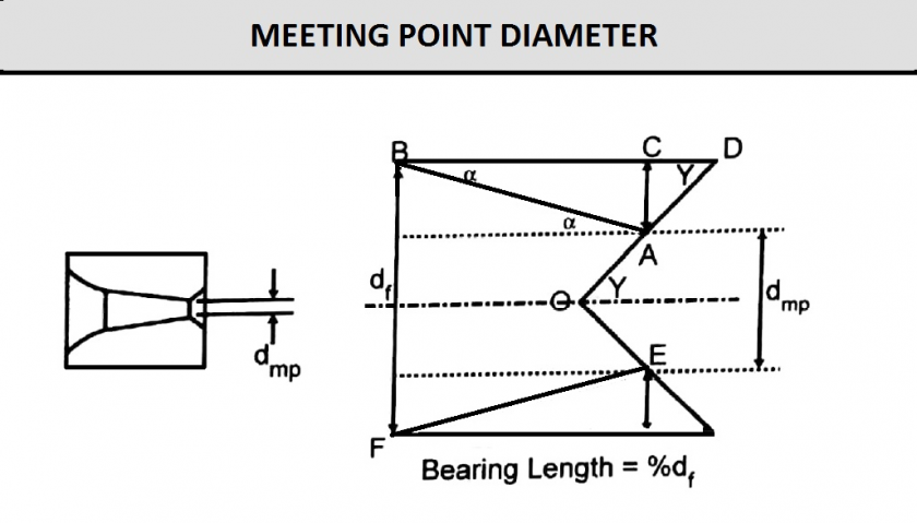
The meeting point diameter is where the approach angle meets the back relief angle before the final diameter and bearing are machined in the die. The approach angle generally is machined in an internal die grinder with a diamond pin to enlarge the angle to the desired meeting point diameter. Meeting point diameter is a function of the approach angle, the bearing length, as a percent of the final diameter, and the back relief angle.
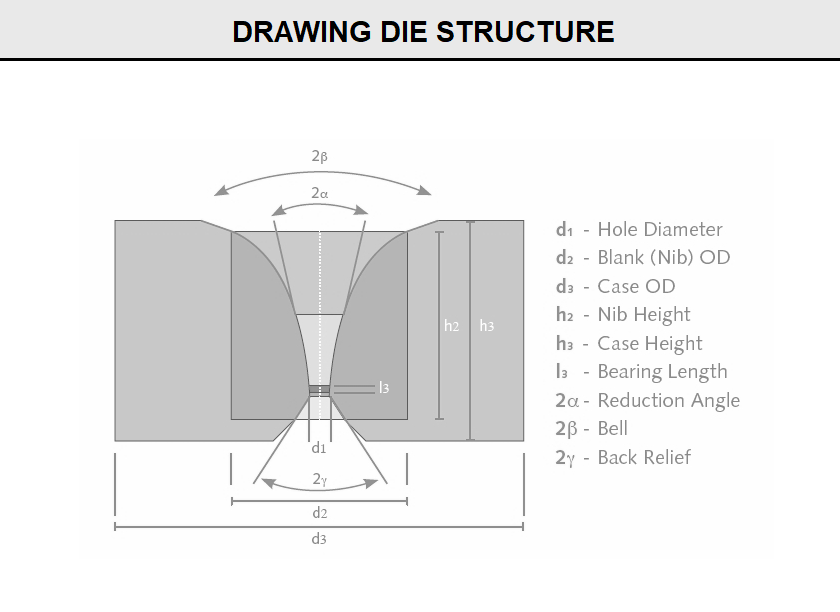
(FigA11) shows the meeting point diameter location in a drawing die nib and the geometry involved in calculating the correct size for a given approach angle bearing length and back relief angle. When finishing the die shown in this figure, the distance (CD) must be removed to form the correct bearing length (BD) and final diameter.
Meeting point diameter (dmp) is usually expressed as a fraction (X) of the final diameter (df ). Consider the geometry shown in (FigA11):
Fig A11
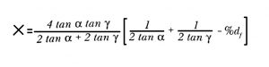
By using these parameters, the fraction X can be calculated as a function of the approach semi-angle (α), half of the back relief angle (∂), and the bearing length (%df), as shown in Eq1
Eq1
Values of the fraction X may be calculated by using a computer program or summarized in a meeting point chart to assist the operator in determining the correct meeting point diameter for a particular die specification. (FigB11) gives the fractions calculated for several included approach angles ( 2α= 8 degree, 10 degree, 12 degree, 14 degree, 16 degree, 18 degree, and 20 degree) and bearing lengths (25%, 35%, 50%, and 66%) for a specific back relief angle ( 2∂ = 90 degree).
Fig B11
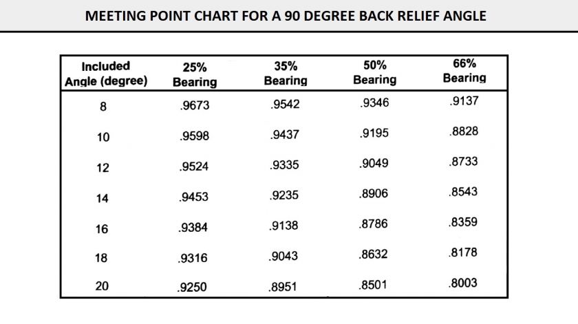
How is this meeting point chart used? Consider that one wants to make a die having the following specifications:
First locate the 12 degree column on the left of the chart. Then locate the 50% bearing column and find the fraction that corresponds with these two parameters. The fraction is 0.9049; therefore, the meeting point diameter is 0.9049 x 0.125 or 0.1131 in. (2.873 mm).
Note: If the back relief angle changes from 90 degree, a different fraction must be calculated by using Eq1.
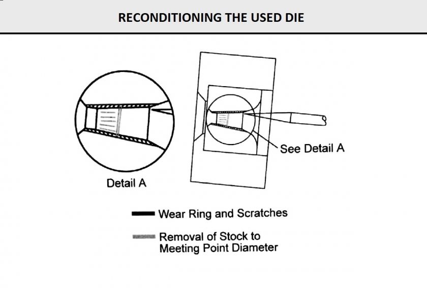
(FigC11) shows how wear ring and scratches in the approach zone of a used die are removed. The shaded area is this figure is machined away to the meeting point diameter of the new die size.
Fig C11
2016 Copyright @ Changsha 3 Better Ultra-hard materials Co.,Ltd.All Rights Reserved
.jpg)